This is a cooler we made in our hostel room during summer season. This cooler is cost effective that it can be built under 1300rs
Thursday, September 22, 2016
PIR controlled electrical appliance
This PIR controlled electrical appliance is very useful to our home.It is so cheap to make...let's try it guys...its only 120rs
Wednesday, March 2, 2016
PROBLEM WITH YOUR DESKTOP COMPUTER NOT HAVING A SERIAL COM PORT HERE'S A SOLUTION WITHOUT USING A SERIAL TO USB CONVERTER
After i closed my CPU and connected the cables. I have googled about my mother board model. I got a circuit diagram showing headers like serial parallel etc with its pin configuration as shown below.
.bmp)
 |
| PHOTO SHOWING A 9PIN SERIAL HEADER |
| SERIAL AND PARALLEL POTS ON PCI CARD |
.bmp)
 |
| CONNECT TX, RX AND GND PINS TO THE HEADERS |
 |
| THE SCREW DRIVER IS FOR POINTING THE HEADER |
The solution is that our mother boards has does not have a external COM PORT but has a internal COM PORT with serial headers consisting of 9 pins as labelled below. This is the serial port having named as COM1. You need top just identify whats the name of the pin like TX,RX,GND etc. connect the wires and take out of the CPU so that you can connect with the external peripherals like ZIGBEE, programming a micro controller,BLUETOOTH etc. with suitable voltage level converters like MAX232 etc or using a potential divider or a transistor based voltage converter.
 |
| THIS PHOTO SHOWS THE RX, TX AND GND PINS TAKEN OUT OF THE CPU |
Now I will show a small demo using TX, RX, GND pins.The serial port has different voltage levels for high and low bits completely different from the TTL logic where 0v is for low bit and 5v is for high bit. The voltage levels are in the range of +3 to +15 volts or the range −3 to −15 volts with respect to the ground/common pin; consequently, the range between −3 to +3 volts is not a valid RS-232 level.
 |
| THE VOLTAGE DIFFERENCE BETWEEN TX PIN AND GND IS NEARLY 12V |


This is the time for testing it. Here i have connected the TX wire and RX wire. What ever you transmit data it is sent via TX wire and received through RX wires as they are connected.

 |
| PHOTOS SHOWING THE TX AND RX WIRES CONNECTED TOGETHER |
Remember that you have to use COM1 as the serial port and the below photos shows how the data is transmitted and displayed on the XCTU window.
 |
| PHOTO SHOWING COOL TERM SOFTWARE |
 |
| SHOWING THE SELECTION OF COM PORT AND BAUD RATE |

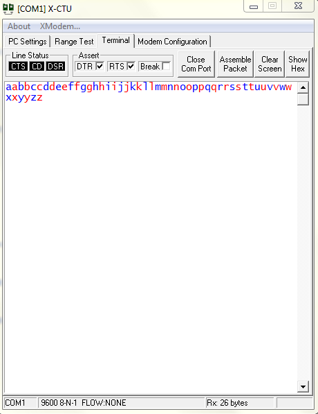 | |||
| THE BLUE LETTERS ARE CHARACTERS TYPED AND TRANSMITTED VIA TX AND THE RED CHARACTERS ARE THE ONES THAT THEY ARE RECEIVED THROUGH THE RX WIRE. |
This is for educational purpose only. Be careful when opening your CPU or ask a expert to to this. We are not responsible for any damage of you computer as they may contain static charges and without any prior precautions you may damage your CPU.
FEEL FREE TO POST YOUR QUERIES AND YOUR EXPERIENCES IN THE COMMENT BOX AS THEY MAY HELP OTHERS.
Friday, September 5, 2014
LIGHT SENSOR
I have tried to use a comparator (LM358) to make a Light Sensor which gives output as high when a certain intensity level is crossed or vice versa but it has not given good output and I don't know the reason. So, I have to go for an alternative because the TASK is important at that time.So I have decided to go for a BJT (BC548) which is cheaper than the previous.This is the circuit which I have designed

Each and every component has its own physical significance. Let me explain briefly
The LED D1 always focus light on the LDR (light dependent resistor) whose resistance varies with light intensity. The potentiometer P1 is used as variable resistor in order to adjust the sensitivity of the LDR to the surroundings. When light falls on theLDR its resistance decreases and make the transistor(Q1) move into active region which may not sufficient to drive the load(L1) less than logic high voltage so I kept a transistor (Q2) for switching purpose operates in either cuttoff or saturation.
Wednesday, September 3, 2014
Simple Water Level Indicator
There is always a problem in our home whenever we switch on the motor and forget to switch it off, after the tank was filled with water and spilled out. So much of water and power is wasted. So, we have decided to solve the problem by making a simple circuit with transistors and a Buzzer.
Let us find out the resistance of our tank water which about 53.7K which is very high.
Let us find out the resistance of our tank water which about 53.7K which is very high.

so we have used a transistor(bc547) for the purpose of amplification in CE mode with beta 110 ~ 220 which may not sufficient for the buzzer to drive directly. So we are using another BJT for switching. The configuration is in the form of a standard Darlington pair, which increases its current amplification capacity hugely.The current through buzzer is β(β+1)Ib(Q1)

The purpose of Resistor and Capacitor is to insert some delay so that the transistor is on for some time (R*C=2.2mS) and so the Piezo Buzzer starts ringing. The whole circuit is given 9V D.C power supply. I have used a 9V battery
Monday, September 1, 2014
UNDERSTANDING THE DATASHEETS OF BASIC GATES AND DECODER IC'S
Many of us use the logic gates for circuit designing. These gates can be made using transistors,diodes,resistors etc. It is not as easy as it is said. But these gates are packed into ic's and are readily available in the market. We can use these ic's for our purpose. Mainly there are two types of ic's. One is TTL and other is CMOS. TTL stands for transistor-transistor logic whereas CMOS stands for complementary metal oxide semiconductors. TTL make use of the transistors and hence the logic levels are for low is "0V" and for high is "5V". But it is always not necessary that only 0V or 5V must be used. Logic low can be in the range of ( 0-0.8)V and logic high can be in the range of ( 2-5)V.
CMOS make use of the MOSFET'S
remaining i ll post it soon.
If urgent i ll make it immediately if you want please tell in comments
CMOS make use of the MOSFET'S
remaining i ll post it soon.
If urgent i ll make it immediately if you want please tell in comments
Monday, September 16, 2013
List of robotics and electronics shops in india

http://www.vegarobokit.com/
http://www.robokits.co.in/shop/
http://www.probots.co.in/
http://www.rhydolabz.com
http://kitsnspares.com/user1/buyproduct.asp
http://www.nex-robotics.com/
http://www.protocentral.com/
http://store.extremeelectronics.co.in/
http://www.bhashatech.com/
http://www.onlinetps.com/shop/
http://www.robosoftsystems.co.in/
http://www.vegakitindia.com/
http://www.sunrom.com/
http://in.element14.com/
http://www.nskelectronics.com/home.html
http://www.makemyhobby.com/
http://www.simplelabs.co.in/
http://in.mouser.com/
http://www.technido.com/store/
http://www.arelab.org/
http://edubotix.in/roboshop.html
http://tenettech.com/
http://www.ventor.co.in/
http://www.digibay.in/
http://www.robosoftsystems.co.in/roboshop/index.php/
http://www.mgsuperlabs.co.in/estore/
http://discovertechcom.com/
http://www.deccanrobots.com/
http://www.rcdhamaka.com/
http://www.intlabz.com/
http://www.embeddedmarket.com
http://www.thinklabs.in/
http://www.digikey.in/
http://www.technophilia.co.in/
http://products.li2.in/
http://www.robomart.com/
http://www.utsource.net/
http://www.thinnkware.com/webshop_page/
http://www.metalmate.in/index.htm
http://www.campuscomponent.com/
http://shop.sumeetinstruments.com/
http://www.technologyahead.com/
http://www.idasystems.net/
http://www.sproboticworks.com/
These are for only educative purpose only. We don't have any contacts with the above stores
and we are not paid for that. Before buying please check the reviews of the products and we are not responsible for the products they sell.
IF YOU KNOW MORE STORES THEN PLEASE WRITE IN THE COMMENTS. THIS MAY BE HELPFUL TO OTHERS AND WILL BE APPRECIATED.
Best websites for new budding electronic enthusiasts

- http://www.technologystudent.com/elec1/elecex.htm
- www.instructables.com
- http://homemadecircuitsandschematics.blogspot.in
- http://www.engineersgarage.com/
- http://www.circuitstoday.com/
- http://www.electronicsforu.com
- http://www.electroschematics.com/
- http://electronicsproject.org/
- http://www.diy-electronic-projects.com/
- http://www.electronics-lab.com/projects/
- http://circuiteasy.com/
- http://www.eleccircuit.com/
- http://www.circuit-projects.com/
- http://www.edgefxkits.in/
- http://www.buildcircuit.com/
- http://www.coolcircuit.com/
- http://www.electro-tech-online.com/
- http://www.aaroncake.net/circuits/
- http://www.edaboard.com
- http://www.circuit-projects.com/robotics/
- http://letsmakerobots.com
- http://www.societyofrobots.com/
- http://www.botskool.com/
- http://101science.com/robots.htm
- http://www.robotroom.com/
- http://www.robotbasic.org/10.html
- http://blog.vinu.co.in/
- http://extremeelectronics.co.in/
- http://www.ladyada.net
- http://pinterest.com/pdavislibrarian/electronics-projects-for-kids/
These are for only educative purpose only. We don't have any contacts with the above websites
and we are not paid for that.
IF YOU KNOW MORE WEBSITES THEN PLEASE WRITE IN THE COMMENTS. THIS MAY BE HELPFUL TO OTHERS AND WILL BE APPRECIATED.
Water Level Indicator/Rain Sensor
There is always a problem in our home whenever we switch on the motor to fill the tank with water. So, we have decided to solve the problem by making a circuit which senses the rain/water
Rain Alarm:
This circuit is built around just two transistors as the main active components
so as to warn about the rain. Also the same circuit can be used as water level
indicator by arranging the sensor at the top of the tank.
Operation:
The
configuration is in the form of a standard Darlington pair, which increases its
current
amplification
capacity hugely. Rain drops or water drops falling and bridging the base with
the positive supply is enough to trigger the alarm. The purpose of Resistor
and Capacitor
is to insert some delay so that the transistor is on for some time (R*C=2.2mS)
and so the Piezo Buzzer starts ringing. The whole
circuit is given 9V D.C power supply.

Sunday, June 23, 2013
CONFIGURING THE XBEE SERIES-2 MODULES PART-1
Today I will show how to set up xbee series_2 modules. After that we will see a small chat application using these series_2 modules.In this tutorial we will see a basic point to point communication.

PARTS YOU NEED:
1.XBEE SERIES_2 MODULES -2no.
2.XBEE USB EXPLORER BOARD (If your computer has a serial port you can use a serial cable instead)
3.USB CABLE IF USB EXPLORER BOARD IS USED
4.X-CTU SOFTWARE (You can download here)
X-CTU software has four tabs like pc settings, range test, terminal, modem configuration as shown below.

For the usb board to be connected to your computer you need FTDI drivers. because the usb board has a FTDI chip. It is a usb to serial converter which opens a virtual com port. So you need these drivers. (you can download here).
After you install these drivers in your computer you can connect your usb board with your xbee plugged in. Now a virtual com port is created with a name like COM2,COM3 etc as it differs from one computer to other. You can see it in your control panel(device manager). I will not discuss it as it is out of scope here. (If you feel any doubts post in the comments section)
Now open the X-CTU software. In the pc settings you can see different COM PORTS as shown in the above figure. My usb board opens port named as COM11 as you can see in the figure. Click on your corresponding port and keep the baud rate, flow control etc as shown as shown in the figure.I configured my xbee to communicate with a baud rate of 9600. After you set these settings click on the Test/Query button. Now you can see a pop up as shown below.

You can see the firmware version, modem type and the serial number. Then click ok. Now your XBEE is connected and ready to be configured. Don't confuse yourself thinking about the firmware version, modem type, serial number. You need to configure one XBEE as a coordinator radio and the other as a router. To avoid confusing write "C" for coordinator and "R" for router on a piece of paper and attach to the the XBEE radios. Take the radio which is named as coordinator and place it on to the usb board. Now this is to be configured as coordinator.
In the X-CTU software click on the Modem Configuration tab. You will see a window like this screenshot as shown below.

In the X-CTU software click on the Modem Configuration tab. You will see a window like this screenshot as shown below.

Now click the READ button. You can see your XBEE radio firmware version and function set and all other options which we will configure now. As my XBEE radio is previously as a coordinator my settings look like this.
CONTINUE TO PART-2

You can see a option like Modem XBEE. It is a type of the modem you purchased. It can be seen on the backside of your modem or this is can be known in the X-CTU software itself when you click on the Test/Query button in the pc settings tab as we done it before. You can select your XBEE Modem type (here it is not necessary as we already click the READ button). (If you select the any other modem type than your XBEE Modem type it will not work and you can brick your XBEE modem. Bricking the XBEE will be posted if you want it. Those who want just request in the comments section).
In the part-2 you will see how to setup the XBEE radio as a coordinator or a router.
Subscribe to:
Posts (Atom)